Expression Pedal Bug
What is the VR09 / VR730 ‘Expression Pedal bug’ ??
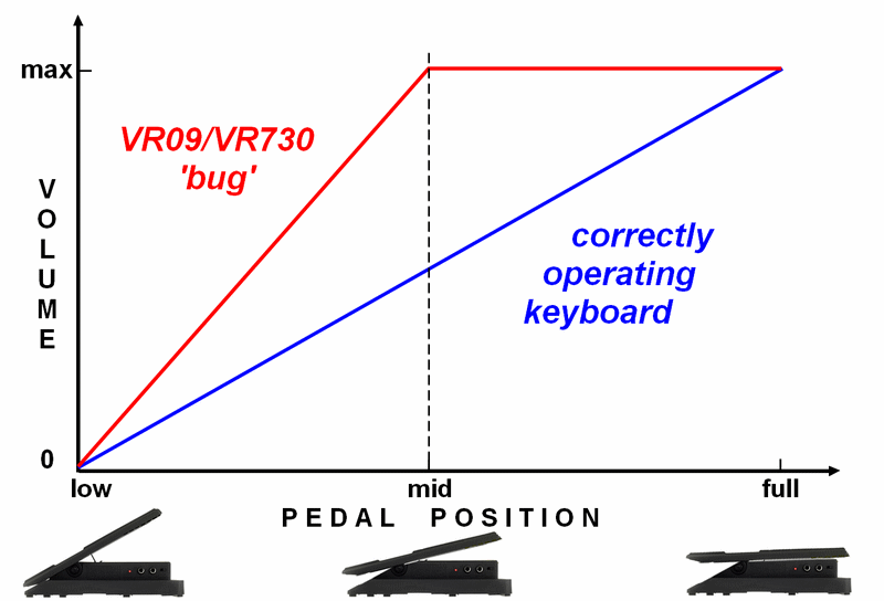
Every ‘normal keyboard’ is following the ‘pedal movement’ correctly, adjusting volume from pedal low position to fully pressed down – not so VR09/730: VR ‘interprets’ pedal mid position already as full volume. The entire volume change from ‘zero’ to ‘full volume’ is happening in the first half of the pedal movement (from pedal ‘low’ to pedal ‘mid’ position), while the 2nd half of pedal movement stays constantly at ‘full volume’. So only one half of the pedal throw is used for volume change – we can say the 2nd half of pedal movement ‘is doing nothing’ – it’s ‘wasted’ IMPORTANT: This VR bug applies to ANY expression pedal model (with only ONE exception: the ‘genuine’ Doepfer FP5)
|
| Note: one can use a ‘Volume Pedal’ instead of an Expression Pedal. As Volume Pedals work differently (e.g. don’t allow ‘organ expression’) they are not covered on this page – for details see Damper&Expression Pedal Guide |
(I) Expression Pedal Midi Converter : Convert your ‘analog’ Expression Pedal to Midi and send to VR
(II) Midi Expression Pedal : Use a ‘Midi Expression Pedal’ instead of an analog pedal
(III) Midi controller/keyboard : Connect Pedal to the controller and route the signal to VR
(IV) Doepfer FP5 : The only Expression pedal which ‘corresponds’ to VR calibration bug
(V) Electric modification of pedal: A simple modification of your pedal to correct the VR voltage bug
(Va) The simple mod : A very simple modification to fix the bug
(Vb) Fine-tune mod of the Pedal: A more sophisticated modification to optimise your pedal
(Vc) Examples
(I) Expression Pedal Midi Converters
Expression Pedal Midi Converters are small boxes that convert your ‘analog’ Expression pedal into “midi expression” messages which are send to VR
The converters can be connected to VR in 2 ways:
a) VR “MIDI-IN” socket: the standard Midi socket
b) VR “PK-IN” (PK-IN is a ‘7pin’ DIN socket compatible to 5pin-DIN midi – just make sure to ‘center’ the plug)
Depending on the model, the converters can be powered by external power-supplies and/or usb-power (e.g. from a phone chager or from the usb-port of VR !)
To configure the ‘midi messages” you need a PC or Mac to run ‘editor’.
For more details see (IV) Midi Expression Pedals and ‘Pedal to Midi’ Converters
For converter models see list of midi expression pedals and converters
|
Converter ‘midi setting’ for VR: The Control Change “CC” for “Expression Pedal” is ’11’ (CC11). For other VR ‘midi functions’ see VR and Classic Midi a) via VR MIDI-IN: VR must be in MIDI MODE 2 (VR menu ‘Midi’) for Expression CC11 use channel 16 other functions (sustain, volume, pitch, modulation, cutoff filter, etc) apply to corresponding channels/VR manuals b) via VR PK-IN: responds to ‘any channel’ can control Expression (CC11), Sustain (CC64) and hidden Atelier functions like rhythm-controls, hawaian “Glide” etc |
(II) Midi Expression Pedal
“Midi Expression Pedals” also bypass the VR calibration bug.
Like “Pedal-to-Midi” converters, midi expression pedals can be connected to VR PK-IN or MIDI-IN (see Chapter (I)).
The pedals can be powered by external power supply, usb-power (e.g. from VR usb-jack) or batteries
For more details see (IV) Midi Expression Pedals and ‘Pedal to Midi’ Converters
For pedal models see list of midi expression pedals and converters
For configuring the Midi Pedal, see chapter (I)
(III) Expression Pedal through ‘midi controller’ (midi keyboard)
When using a midi controller with VR (e.g. as lower manual) equipped with an (eventually configurable) ‘expression/pedal socket’, connect the pedal to the controller and ‘route’ the midi signal to VR
The principle of using expression via “midi-controller” is similar to ‘pedal to midi converters’
Instead of buying an extra converter, why not ‘upgrading’ to a full midi keyboard that can also be used as ‘lower manual’?
For configuring the controller ouput, see chapter (I)
(IV) Doepfer FP5
The Doepfer FP5 expression pedal has a special ‘voltage calibration’ that uniquely works for Doepfer Midi Controllers. By ‘conincidence’ the ‘Doepfer Calibration’ is the same as on ‘buggy’ VR09/730, so it’s the only pedal that works correctly (after changing ‘polarity’) with VR ‘out of the box’. The Doepfer pedal is neither cheap and nor available everywhere – and its a ‘one shot wonder’ as it cannot be used with any other key than VRs and Doepfer controllers.
Additionally, its polarity must be inverted to work on VR – by resoldering the cable or “TRS adaptor cables” (see Damper&Expression Pedal Guide)
(V) Expression Pedal modification
Analog Expression Pedals can be modified electrically by ‘simple’ means: 2 resistors (or trim pots) and a soldering iron.
After the ‘mod’ the pedal works uniquely with VR09/730 (and Doepfer controllers ;)) but the mod can be reverted any time (e.g. when selling VR)
An alternativ to ‘modding the pedal’ itself is building a little ‘adapter’ (see end of this site)
(Va) The ‘simple’ mod
The ‘simple mod’ is a simplified modification (for very basic electric skills and ‘a soldering iron’) for standard pedals with 10-12kOhm, 20kOhm and 50kOhm potentiometers
Chapter (Vb) explains how to ‘fine tune’ and ‘perfectionise’ pedal throw for VR dedicated for those with higher knowledge (and equipment) in electrics
What you need:
- an expression pedal: this can be any pedal with a linear potentiometer (10kOhm, 20kOhm, 50kOhm, etc)
- resistors (buy at local or online electronic discounter, or recycle from old circuit bords)
- soldering iron
- very basic skills in soldering/electrics – or a skilled friend …
The fix, electrically explained
An expression pedal is basically a ‘pot – a ‘potentiometer’ – a variable resistor.
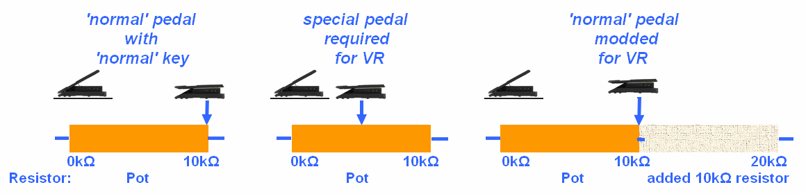
In a ‘normal’ pedal, with the pedal set to minimum, the pot has zero Ohm (resistance). With the movement of the pedal the resistance increases, up to full resistance when ‘fully pressed down’.
Every ‘normal keyboard’ is following the resistance correctly, adjusting volume from zero (or low) to full – not so VR09/730: VR ‘interprets’ already the half of resistance (pedal mid position) as full volume, so the volume change from ‘zero volume’ to ‘full volume’ happens in the first half of the pedal movement from pedal ‘low’ to pedal ‘mid’ position while the 2nd half of pedal movement stays constantly at ‘full volume’.
There is actually only one ‘stock pedal’ that ‘fits VR calibration’: Doeper FP5, a genuine pedal that only works with Doepfer master controllers – and VRs (see chapter IV)
The mod consists of adding an extra resistor to the pot: with pedal fully pressed, VR is ‘seeing’ the resistance only at ‘half of combined resistance of pot + extra resistor’, so ‘full volume’ is reached at the end of pedal travel – as it should be
Left graphics shows a “10 kOhm’ pedal (like Roland EV5 or M-Audio EX-P). Centered graphics is a ‘genuine pedal’ (Doepfer FP5) with ‘VR compatible pot’. Right graphics is the modified “10 kOhm pot + 10kOhm resistor” pedal, that behaves like a ‘genuine VR pedal’:
The mod
The mod consists of 3 tasks:
- adding a resistor to correct the ‘pot resistance’ (‘the bug’)
- adding a 2nd resistor to fine-tune the ‘minimum volume pedal position’
- an eventual correction of the ‘polarity’ of the TRS plug (this is not necessary for pedals that already have the correct polarity like Roland pedals or a ‘polarity switch’)
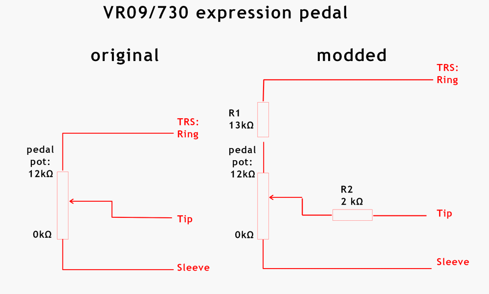
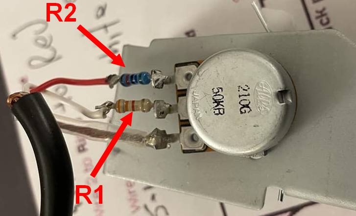
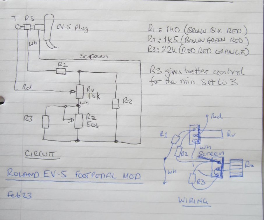
We take a look at a circuit diagramm: the picture shows a pedal with 12 kOhm pot (like M-Audio EXP, Nektar), the added resistors R1 and R2 are shown with values that give the best result for the pedal:
- Resistor R1 fixes the ‘potentiometer issue’
- Resistor R2 fine-tunes the ‘low volume’ position of the pedal
- The wiring shows the correct polarity for VR: R1 must go to the ‘ring’ of the TRS plug, R2 must go to its ‘tip’.
Recommended values for resistors R1/R2
For identifying the ‘potentiometer type’ of your pedal, get the spec sheet of the pedal (or use a voltmeter to measure the resistance between the 2 lateral pins of the potentiometer)
| Potentiometer | R1 | R2 | Examples |
| 10-11 kOhm | 11 kOhm | 1.5 kOhm | Roland EV5 |
| 12 kOhm | 13 kOhm | 2 kOhm | M-Audio EXP, Nektar NX-P |
| 20 kOhm | 29kOhm | 5 kOhm | Bespeco pedals |
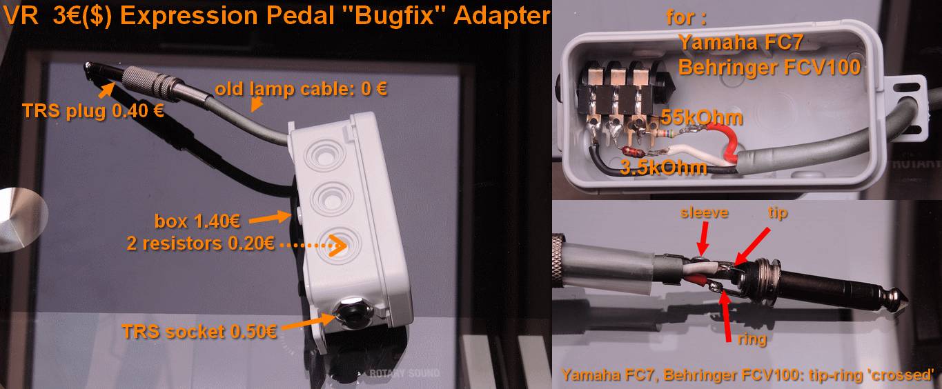
| 50 kOhm | 55 kOhm | 3.3 kOhm | Behringer FCV, Yamaha FC7 |
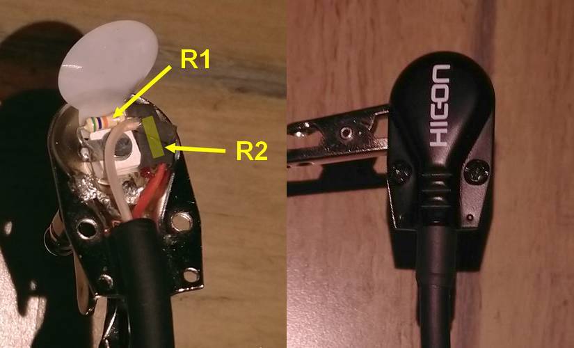
Mod inside the pedal
The most simple way is to open the pedal and solder resistors R1 (to TRS-ring) and R2 (to TRS-tip) directly to the wires as shown in the picture (the ‘sleeve’ of the TRS plug is usually connected to the copper ‘cable shield’ wire)
Which of the wires go to TRS-plug ‘tip’ or ‘ring’ – well, you have to figure this out: either by using a voltmeter or the ‘spec sheet’ of the pedal:
e.g. Roland pedals have the ‘good wiring’, Yamaha FC7 and Behringer FCV “Mk1” need ‘tip’ and ‘ring’ wires to be flipped. Pedals with a ‘polarity switch’ (M-Audio EXP, Nektar, Behringer FCV “Mk2”) don’t need attention: if the pedal behaves ‘strange’ just flip the switch.
 |
Mod of Yamaha FC7. General rule for pedals with ‘simple electric construction’ that allow to solder the resistors directly to the ‘potentiometer’: R2 has to be soldered to the potentiometer ‘center pin’ and must be wired to the tip of the TRS plug R1 has to be soldered to the lateral potentiometer pin that is _not_ connected to the ‘cable copper shield’ and must be wired to TRS ‘ring’ |
Mod the TRS plug
Alternatively you can add the resistors into the TRS plug (eventually cut the original plug and add a custom plug). The picture shows a ‘Hicon angled’ plug modded for Behringer FCV:
Build an ‘adapter’
An ‘adapter’ has the advantage that your pedal stays unchanged (and can still be used on other keyboards). An example of a ‘low cost adapter’ is shown at the end of this page
(Vb) Fine-tune mod of the Pedal
The following requires a deeper understanding of electrics and some additonal tools like a voltmeter.
It will adjust the resistor values to exactly match your expression pedal model.
What you need:
- an expresson pedal
- 1 or 2 stereo TRS (6.3mm) plugs and a ‘stereo cable’ depending if the pedal comes with a cable or not
- resistors and or if possible 2 ‘trim potentiometers’
- soldering iron
- Volt/Ohmmeter
- recommended: laptop/tablet/PC with midi monitor app + usb-cable to connect to VR to measure the ‘expression CC values’
- basic skills in electrics and soldering or a skilled friend …
The bug – electric analysis
An expression pedal is a simple voltage divider using a potentiometer that is driven by the pedal.
Keyboards use a constant ‘reference voltage’ and a ‘working voltage’ set by the pedal potentiometer. The pedal position changes the ‘working voltage’ between zero and the reference voltage, which controls the ‘keyboard volume’
On the VR, the reference voltage is 5 Volts (precisely: 4.85 Volt)
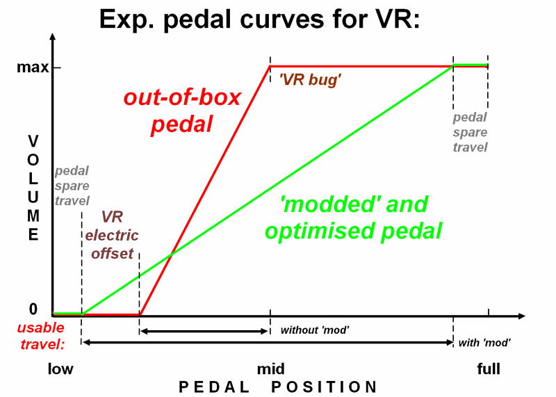
In an ideal case, when the working voltage approaches zero, the volume becomes zero. When pedal is pushed to ‘full’ and the working voltage reaches the ‘reference’, the volume becomes maximal.
The problem is that VR has a faulty calibration:
- maximum volume is already reached when the ‘working voltage’ is at ca. 1/2 of the reference (ca. 2.5V – 2.7V) which corresponds to the pedal being at ‘mid position’. So you can use only the ‘first half’ of the pedal travel, the ‘2nd half’ is just on constant (max) volume
- minimum volume is already reached when the ‘working voltage’ is 0.3 – 0.7 Volt (depending on the pedal type. All keyboards have this ‘electric offset’ for zero volume but on the VR the value is quite high and more precious millimetres of pedal travel are lost
- as a result the ‘usable travel’ of an ‘out-of-the-box’ pedal is heavily reduced, in case of short throw pedals to ca. 1cm!
The mod consists in adding resistors to the potentiometer of the pedal to correct the relationship between zero and full volume: the pedal shall not reach ‘1/2 reference voltage’ (which corresponds to VR full volume) at its mid position but at the fully pressed position.
We also optimise the ‘offset voltage’ (which corresponds to VR zero volume) to regain as much of the ‘idle’ at the beginning of a ‘pedal press’
First let’s take a look the signal path of the pedal and its TRS plug.
A TRS plug has 3 sections: ‘tip’ is the – guess what – tip of the plug, ‘ring’ the middle section, ‘sleeve’ the base section
In the diagram, the ‘reference voltage’ is between sleeve and ring and the ‘working voltage’ is between sleeve and tip
As said, in the case of the VR, when the pedal potentiometer is in half position the working voltage is at ca. 2.5V and the VR interprets this as maximum volume.
The trick is to add a resistor (R1) into the ‘reference path’ that has approximately the same value as the full resistance of the pot (we call it R0).
Now when the pot is set to 100% (full pedal travel) the working voltage is 100% of R0 (pot) divided by 2 times R0 (pot + R1), resulting in 1/2 of the reference voltage = 2.5V – which the VR interprets as ‘full volume’ – but this time at ‘full pedal travel’. Problem fixed.
The above explains the ‘principle’ of the mod. In reality things get a bit more complicated because pedals have a small resistor (so called shunt resistor) in the Tip-path, usually 1 kOhm. Some pedals even have an additional ‘volume offset’ potentiometer (in the tip path) that allows to set the minimum volume to a higher level (this is useful for using the expression pedal like a switch between ‘accompaniment’ and ‘solo’). Modding this shunt resistor can optimise the pedal travel on the ‘zero volume’ side.
The wiring digram shows the two ‘additional’ resistors for the ‘maximum volume issue’ (R1) and the ‘minimum volume optimisation’ (R2).
The indicated values are best values for the M-Audio EXP pedal, giving you the longest possible ‘working travel’ of the pedal.
Your pedal might be different and you have to figure out the values by experiments: you can use little ‘trim pots’ for R1 and R2 that you can exactly calibrate for the best setting. Calibration can be done by ear, which is not very precise. The far better way is to attach the VR to a midi monitor e.g. Windows laptop + MidiOX and follow the midi values of the ‘expression’ pedal (0 = zero vol, 127 = max vol)
NOTE: the ‘volume offset pot’ of some pedals can be used instead of R2 but there’s a risk that you accidentally lose its correct position.
Let’s modddd
Preparation
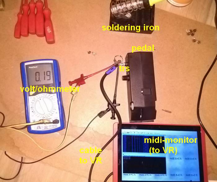
On the VR-menu, set the expression pedal curve to ‘3’ (you can change this back later)
If possible connect the midi-monitor to the VR-5-pin-out.
Solder the trim pots as resistors R1 and R2 into the tip and ring signal path between cable and pedal: you can do this a) in the pedal itself b) in the TRS jack that will be plugged into the VR or c) like shown on the photos in the TRS jack that is plugged into the pedal if the pedal has no fixed cable:
Dimension of trim pot R1 = 1.5 * R0 (if you have no pots in this size, use a smaller one + preresistors) Connect the cable to VR and expression pedal, test if the volume changes, eventually check the ‘midi expression control change (CC7)’ signal on the midi monitor
Dimension of trim pot R2 = 10 kOhm
Connect the voltmeter to the ‘tip’ side of the VR: you must measure the ‘tip’ voltage that is at the VR
Set trim pot R1 to ca. R0 and trim pot R2 to 0.
Calibrating
- Move the pedal to maximum and adjust trim port R1 until the sound volume just starts not to decrease (ca 2.5 – 2.7 Volt depending on the pedal type)
- Move the pedal to minimum and adjust trim port R2 until the sound volume just starts not to increase (ca 0.3 – 0.7 Volt depending on the pedal type)
- Readjust R1, R2
NOTE: to estimate the volume by ear is very difficult. It’s strongly recommended to use the midi monitor to verify the expression volume control changes
The pedal should now work on it’s full travel.
Next we add some ‘security margin’: resistances won’t be 100% exact every day because of mechanical tolerances, sweat on the plugs, constellation of planets…
- Move the pedal to maximum volume and adjust trim port R1 until the tip voltage has increased by ca. 0.10 Volt (ca 2.6 – 2.8 Volt depending on the pedal type)
- Move the pedal to minimum volume and adjust trim port R2 until the vip voltage has decreased by ca. 0.10 Volt (ca 0.1 – 0.6 Volt depending on the pedal type)
IF you have done the modd within the pedal and you opt for keeping the trim pots, the work is done
You can also replace the trim pots by constant resistors (necessary if you did the mod within the TRS plug with limited place): unsolder the trim pots, measure their resistance, find (or combine) equivalent resistors.
Values for Expression foot pedals like Behringer FCV and Yamaha FC7 with 50kOhm potentiometer and 1kOhm R2 shunt resistance:
| Volume | reference tip voltage | tip voltage ‘with margin’ | trim pots (with ‘margin’) | resistors used |
| max | 2.70V | 2.84V | 59.7kOhm | R1 = 55 kOhm |
| min | 0.30V | 0.20V | 3.49 kOhm | R2 = 3.3 kOhm |
Values for Expression foot pedals like M-Audio (and eventually EV5) with with 12kOhm potentiometer and 1kOhm R2 shunt resistance:
| Volume | reference tip voltage | tip voltage ‘with margin’ | trim pots (with ‘margin’) | resistors used |
| max | 2.50V | 2.6V | 13kOhm | R1 = 13 kOhm |
| min | 0.70V | 0.6V | 2.0kOhm | R2 = 2.0 kOhm |
(Vc) Examples
(Click on the pix to open larger images)
- This is the mod put inside a flat HiCon TRS plug of the pedal cable, using constant R1 and R2 (R2 is covered by isolation and not visible) instead of modifying the pedal itself. The example shows resistors (R1=13kΩ, R2=2kΩ for M-Audio / EV-5:

- This is how Robert Leshtz’ directly modded the potentiometer of his Yamaha FC7:

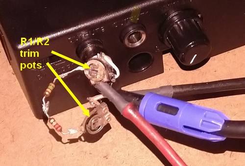
- This is David Ross’ elaborated circuit for Roland EV-5 pedal, optimising the ‘expression curve’:
- This is a 3 €/$ adapter box. The example shows the resistors for Yamaha FC7/Behringer FCV100 inclucing the Tip-Ring inversion. Pedals like M-Audio EXP and Roland EV5 (with 10kOhm potentiometer and no Tip-Ring inversion) would be ca. 13kΩ at ‘ring’ and 2 kΩ at ‘tip’: