Triple Jacks for Leslie Control: on/off – fast/slow – brake
Many thanks to David Webster for this fantastic guide!
This is a guide to fitting sockets for external control of Leslie speed by a switch pedal, together with sockets for control of Leslie on/off and brake. Adding all three gives hands free control of the Leslie similar to the original Hammond half moon switches or knee levers.
This builds on previous posts on the Facebook group by Jack Lyon and further description and notes by Frank Vcombo-Editor – see https://v-combo.webspace.rocks/leslie-switch for Franks text and photos. Credit to both for the ideas and apologies if there is anyone else’s contribution I haven’t credited.
There’s a slight complication in externally controlling the brake function as is not controlled by a switch but by the mod lever operating a potentiometer. This isn’t quite so straight forward to implement but like most things – if you’re determined…..
Now the technical bit for implementing the brake control using a switch – you can skip this unless you are interested in how it works.
The arrangement of the brake switch needs to replicate the actual change in value of the potentiometer resistance when the mod lever is pushed forward (measurement shows it drops from 5k to 1.2k) rather than simply dropping to zero which would occur if a simple pedal switch was wired across the potentiometer. This is fairly simple to achieve by putting a resistor of an appropriate value in series with the pedal switch and thus in parallel with the potentiometer when the switch is closed. The effect of the second resistor in parallel is to reduce the effective resistance in the circuit and this needs to be to the value that trips the brake. The potentiometer resistance in the rest position was measured at 5k and when pushed forward 1.2k. A quick application of Ohm’s law shows that a 1.5k resistor in parallel will give the necessary drop to 1.2k (or near enough anyway) across the board contacts. A quick test (always a good idea) proved it worked. In fact a few tests showed that the value is not critical but always best to keep things as they are if possible so now on to the actual work………
It is important to stress that none of this is endorsed by Roland or their distributors. Opening up a keyboard is generally not approved by the manufacturer so don’t expect help from them if anything goes wrong. Any damage you cause will be down to you to fix or pay someone to do it, your warranty may be voided.
The information provided here isn’t full detailed instruction and I assume that you have some experience in opening keyboards and the like and can work out basic wiring. You will require care, a basic level of skill and be able to solder connections to printed circuit boards. I don’t accept responsibility for any damage you may cause or injury sustained.
Before you start make sure you have backed up any saved registrations and settings then remove all power (including batteries if fitted).
First remove the base of the keyboard. There are details of how to do this – see https://v-combo.webspace.rocks/opening-and-removing-the… for information on opening a VR730 to clean the key bed (just open the keyboard, you don’t need to remove the actual key bed from the base for this project)
VR09 & VR09B – see https://v-combo.webspace.rocks/leslie-switch for Franks text and photos on opening and fitting a fast/slow switch outlet to a VR09
With all the workings visible, identify the switch circuit board and the mod lever arrangement – Photo 1.
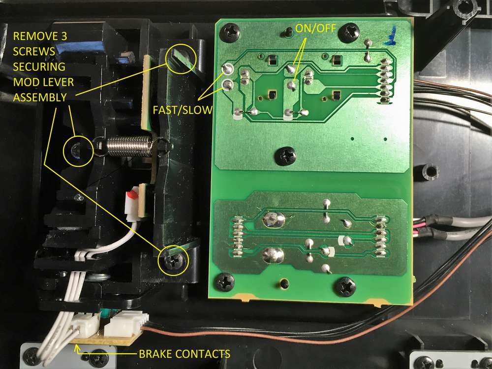
Photo 1 Switch Connection Points 1
Because of the position of the mod lever board it is best removed to solder the connections. Remove the 3 securing screws and lift out the whole assembly. It is easier though not essential if you disconnect the wiring plug connecting it to the main circuit boards. With the mod lever assembly removed, the connection points for the brake control can be identified on the circuit board – Photo 2.
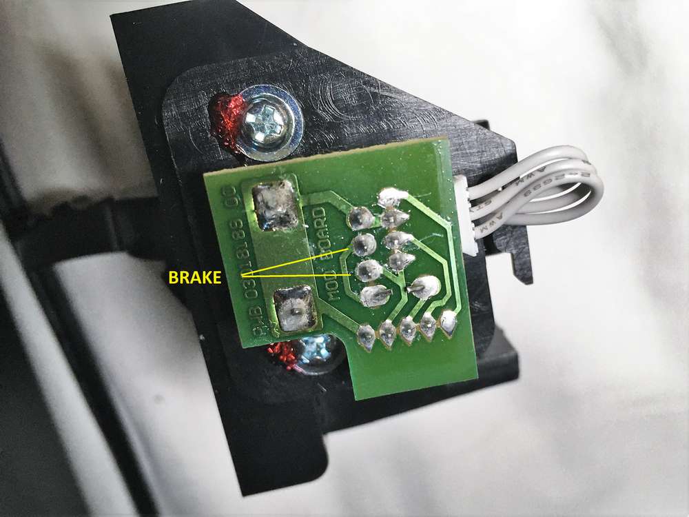
Photo 2 Switch Connection Points 2
When making soldered connections between circuit boards, I usually use a plug connector to allow disconnection (as the manufacturers do) – makes it much easier should it prove necessary to dismantle in the future. Fitting the plug connector and using a connection strip board is not essential, the wiring could just go direct to the sockets (but remember to include the resistor in the brake circuit). I use JST type connectors are available with with a standard 2.54mm pin spacing to suit strip board and wires already attached – Photo 3
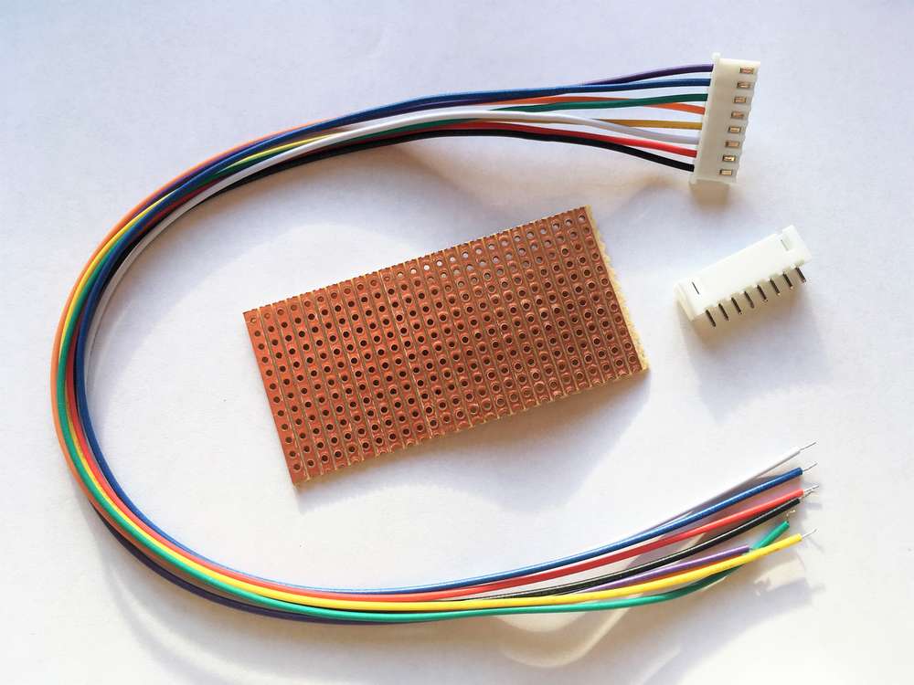
Photo 3 JST Plug and Stripboard
The JST socket is soldered to a piece of strip board and wires from the board connect to jack sockets on the rear panel. The layout of the strip board is quite simple and shown in diagram 3A.
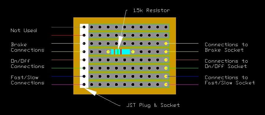
Photo 3A Connection Board Layout
This is where the resistor for the brake switch connection is fitted in the circuit. The strip for the yellow connection is cut and the 1.5k resistor fitted
JST plug lead shown connected to the on/off and fast/slow points. There are 2 unused wires (red and black) as the plugs I had to hand were 8 way – Photo 4, and the brake connections to the mod lever board – Photo 5
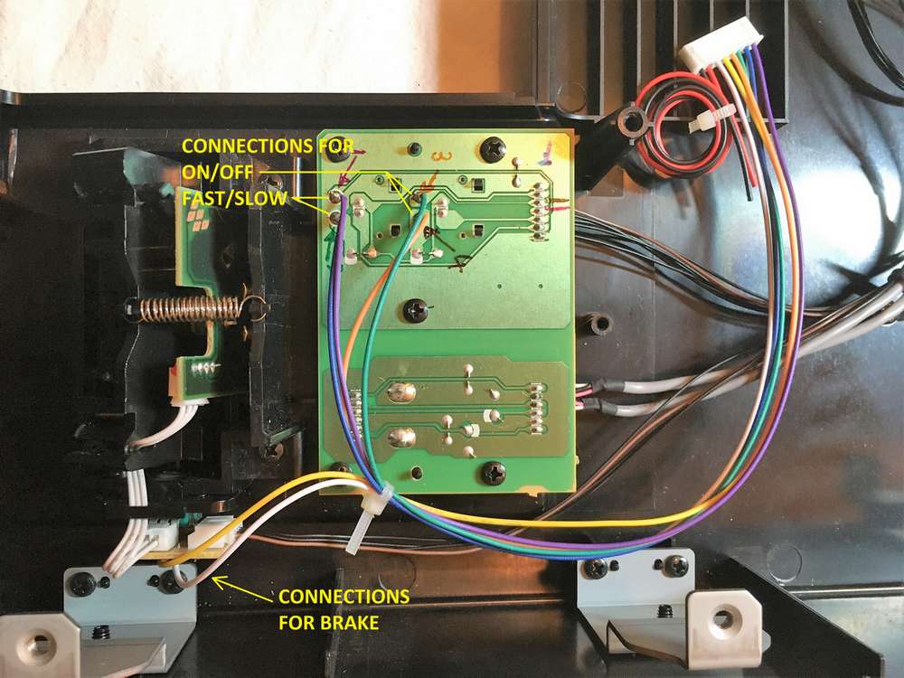
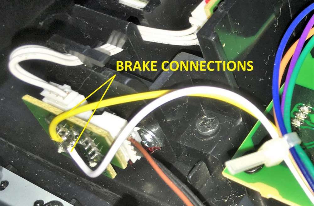
Photo 4 Connections 1
Photo 5 Connections 2
The strip board with JST plug connected and wires to connect to jack sockets on the rear panel. The strip board has been fixed in place using hot melt adhesive (double sided pads will also work well.) Note the resistor is fitted to the board but hidden under the wiring – Photo 6
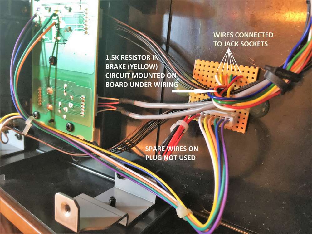
Photo 6 Connection Board
The 3 jack sockets are fitted to the rear panel in a location where they will not interfere with any other parts of the keyboard. For appearance sake avoid the logos on the back panel. Drill holes to suit the sockets used supporting the rear panel to prevent it cracking. A piece of masking tape with the hole positions marked will help prevent the drill bit slipping. Fit the sockets and wire back to the strip board – Photo 7
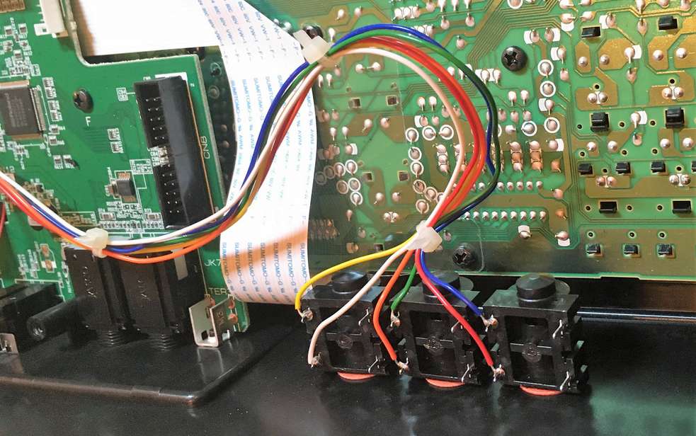
Photo 7 Jack Sockets Fitted
Now is a good time to temporarily reconnect the keybed and test everything is working as it should.
The wiring should then be neatly routed, tied and clipped to avoid the back of the keybed, making sure it doesn’t interfere with the key movement – Photos 8 & 9
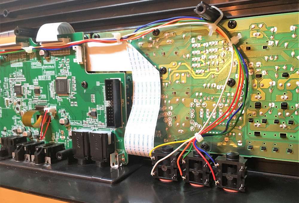
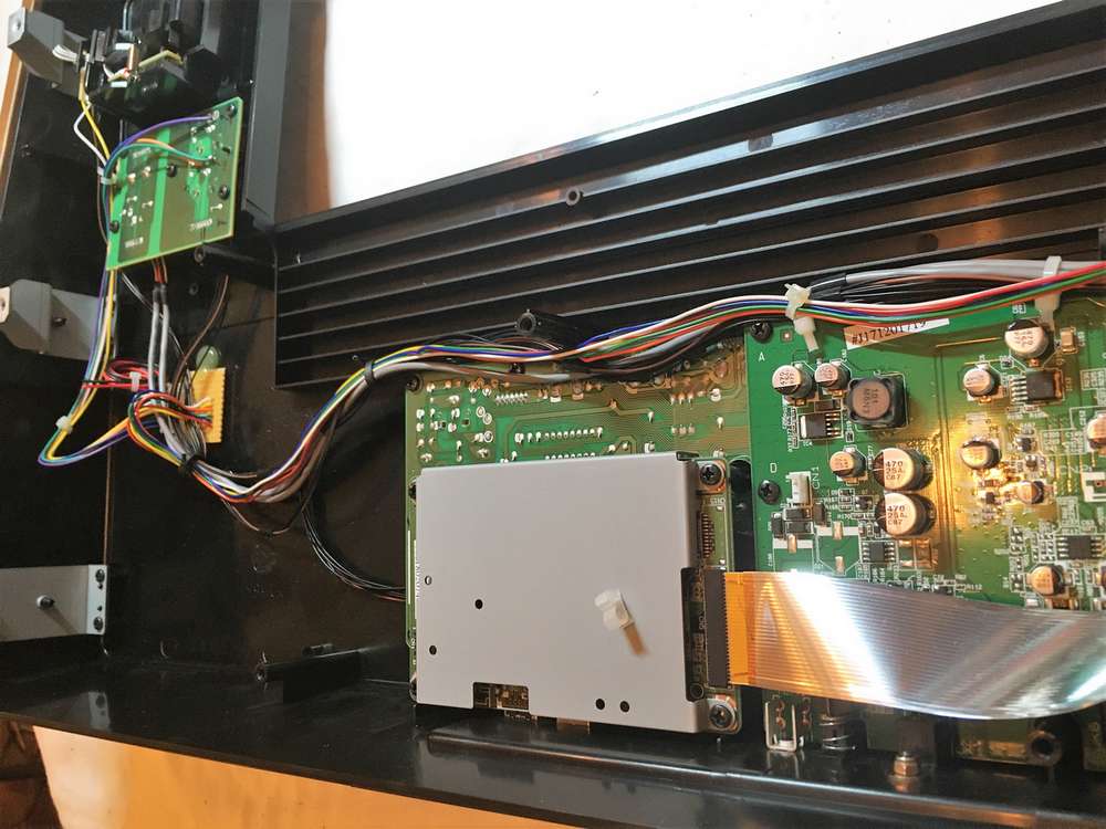
Photo 8 Wiring Routed 1
Photo 9 Wiring Routed 2
Reassemble the keyboard and it is good to go. Suggested position of the sockets on a VR730 is shown in Photo 10. It’s useful to label them which I still have to do. I shall probably colour code them to match the cables/plugs I use to connect the pedal switches

Photo 10 Jack Sockets External
Points to note –
-
Switches should be momentary normally open. Standard keyboard pedals work well as will guitar type stomp box switches so long as they are normally open momentary action. Be aware that the damper pedal for the VR is normally closed so will not work unless it is a universal type with a changeover switch.
-
The brake function triggered by the mod lever only operates in organ mode, when in piano or synth mode it activates the modulation. Using the pedal switch to control modulation is on/off – no variable control but as the lever has a short throw it doesn’t really allow much control over modulation level so little practical difference.
-
In piano or synth mode the other two pedals will still control the Leslie function as the buttons do. This can be very useful if you want to add a Leslie effect to piano (Pink Floyd Echoes or Led Zeppelin No Quarter).
-
The Leslie on/off and fast/slow buttons and the mod lever will continue to operate as normal whether a pedal is plugged in or not and can be used as well as the pedal switches.
-
The plug/socket used for the connector strip board are JST XH with 300mm cable ready attached. Widely available and popular with model builders but any plug/socket that fits the strip board can be used. I had 8 pin handy but only a 6 pins are needed so 2 pins were left unused. Ideally using a 4 pin and a 2 pin would be a better solution.
-
There is no common ground between any of the connections so each socket must be isolated from the others. Don’t use metal bodied sockets unless they electrically isolated, don’t substitute a stereo socket or use a twin pedal connecting through a stereo plug.